| Home Page |
| Latest News |
| GB3FM |
| GB3FN |
| GB3FNM |
| GB3FRS |
| GB3FX |
| GB3SN |
| Coverage |
| The Group |
| Supporters |
| Constitution |
| How to Join |
| Help Us! |
| Radio Links |
| Site Tour |
| Contact Us |
GB3FM - GB3FN - GB3FNM - GB3FRS - GB3FX - GB3SN
GB3FRS Beacon description
GB3FRS is located, together with the GB3SN repeater, on the Boyneswood water tower at Four Marks, near Alton, Hampshire at:
National Grid Reference; SU673361
QTH Locator; IO91LC
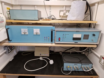
The equipment for the 1296MHz beacon GB3FRS is housed in 3 units.
- The first is the signal source/ driver. This uses a custom made PLL unit from DF9NP. This is fed with a GPS derived 10MHz reference. The output level of the PLL is about 10dBm and this is raised to about 20dBm by a small Chinese gain block. That feeds a driver stage using an RA18H1213G module. This was chosen as varying the gate control voltage allows the output power to be adjusted over a wide range. The output of this module is fed through an inter digital filter to the next unit.
- The second unit is the power amplifier. This uses a module from SG-labs rated at 25W max output. The incoming signal is further filtered then applied to the PA. The output of the PA is fed through a directional coupler to sample the output power. The sample is fed to a detector followed by a front panel moving coil meter driver board to allow output power to be displayed. The output of the directional coupler Is fed to the next unit.
- The final filter is a precision inter digital filter made by PE1RKI. This has a high level of attenuation of any out of band products. The output of this filter is fed via a lightening trap to the antenna feeder.
The antenna feeder is ~ 20m of LDF4-50. Sadly, this has deteriorated and has higher loss than expected.
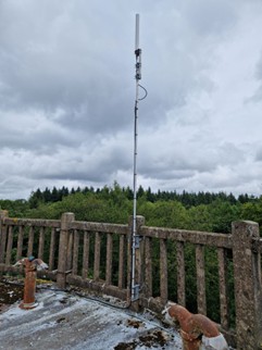
Finally, the antenna is an Alford Slot, mounted about 3m above the top of the water tower.
Currently the PA is being run at 12W output to deliver 3.5W to the antenna which has a maximum of 7dB gain to approach the intended 25W ERP.


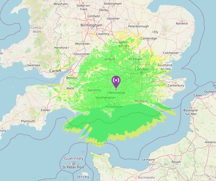
GB3FRS Antenna GB3FRS Equipment GB3FRS Coverage Map
[Click any image to enlarge]